2026 Best Rotary Actuator Symbol Guide for Global Buyers?
Choosing the correct Rotary Actuator Symbol is a small decision with major consequences. A misplaced arrow, port mark, or rotation indicator can distort an entire pneumatic or hydraulic schematic. Global buyers often review symbols before reviewing dimensions, materials, or supplier claims. That practical step deserves more attention.
ISO 1219-1 provides internationally recognized graphical rules for fluid-power circuit diagrams. IEC 60617 also supports standardized electrotechnical symbols and searchable symbol references. Meanwhile, recent market reports from Grand View Research and MarketsandMarkets identify continued growth in industrial automation, robotics, and motion-control equipment. Their findings suggest stronger demand for clear documentation across factories, distributors, and engineering teams. The reports are useful, but they do not remove every interpretation problem.
Peter Rohner, author of Fluid Power Logic Circuit Design, offers a practical principle: “A circuit should explain its function before it explains its parts.” That principle fits Rotary Actuator Symbol selection remarkably well. Buyers need to recognize motion, control direction, ports, and energy flow within seconds. A symbol should work on a printed drawing, a CAD screen, and a supplier’s product page. It should not require guesswork.
This 2026 guide examines common symbol variations, ISO-based notation, pneumatic and hydraulic applications, and regional documentation habits. It also compares symbols with real actuator behavior, including rack-and-pinion rotation, vane movement, and limited-angle positioning. Some diagrams remain confusing, even when technically acceptable. That gap is worth questioning. Reliable purchasing depends on more than a familiar icon; it depends on accurate interpretation, traceable standards, and careful engineering judgment.
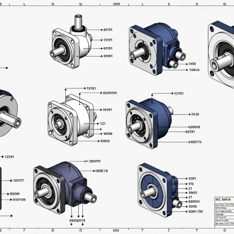
Rotary Actuator Symbols: Definitions, Shapes, and Core Functions
Rotary actuator symbols translate motion into a compact visual language. Under ISO 1219-1, a circular symbol commonly represents rotary movement, while an arrow shows rotational direction. A two-headed arrow usually indicates reversible operation. Additional marks may identify pneumatic, hydraulic, or electric energy. The exact shape can vary across drawing standards, so experienced engineers verify the legend before ordering equipment.
The core function is controlled angular motion. Designers check torque, rotation angle, speed, load inertia, and mounting position. A quarter-turn actuator may control a valve, while a rotary drive can position a robotic joint. The International Federation of Robotics reported 541,302 industrial robots installed worldwide in 2023. That figure reflects the growing need for accurate rotary motion in automated systems. The U.S. Department of Energy also reports that compressed-air systems may waste 20% to 30% of supplied energy through leaks and poor maintenance. A symbol alone cannot reveal this efficiency risk.
Tips: Read the arrow first. Check the energy symbol next. Confirm whether the actuator provides continuous rotation or limited travel. I also compare the drawing with the technical datasheet, because symbols are not always perfectly consistent. This small step prevents a costly mismatch between torque demand and actuator capacity. A neat diagram can still hide an undersized mechanism.
How to Read Rotary Actuator Symbols in Technical Diagrams
2026 Best Rotary Actuator Symbol Guide for Global Buyers?
How to Read Rotary Actuator Symbols in Technical Diagrams
A rotary actuator symbol shows controlled shaft movement inside a fluid-power circuit. Under ISO 1219-1, the symbol should be read with its ports, arrows, and control elements. A curved arrow usually indicates rotation. Two connected ports often represent a double-acting actuator. One port may indicate single-acting operation, while a spring shows the return action. Do not confuse flow arrows with shaft direction. They describe fluid movement, not always the final rotation.
The International Federation of Robotics reported 541,302 industrial robots were installed worldwide in 2023. That figure shows why accurate diagram reading matters in expanding automation systems. Check the symbol beside valves, pressure controls, and end-position sensors. These nearby details reveal how the actuator starts, stops, and reverses. An angle label may show 90° or 180° travel. Torque, load, and cushioning details usually appear in specifications, not inside the basic symbol. My practical mistake was once treating a curved arrow as a fixed rotation direction. The circuit later showed reversible operation.
Tips: Trace each line from the energy source to the actuator. Count the ports. Identify the valve’s normal position. Look for spring, exhaust, flow-control, and sensor marks. Then compare the drawing with ISO 1219 and the actuator datasheet. Some diagrams remain simplified, so one interpretation may still need confirmation from the designer.
Symbol Variations for Pneumatic, Hydraulic, and Electric Actuators
2026 Best Rotary Actuator Symbol Guide for Global Buyers
Symbol Variations for Pneumatic, Hydraulic, and Electric Actuators
Rotary actuator symbols show movement, power source, ports, and control direction. Pneumatic symbols usually connect to air lines and directional control valves. Their simple diagrams can hide important details, such as single-acting springs or adjustable rotation limits. Hydraulic symbols often use thicker circuit lines and fluid-control elements. Pressure ratings, return paths, and contamination risks deserve attention. The symbol alone is not enough.
Electric actuator symbols commonly include a motor, gearbox, wiring, and feedback connection. A feedback mark may indicate position sensing, but it does not always specify the signal type. That gap matters. In practical specification reviews, I compare the symbol with the actuator datasheet, wiring diagram, and mounting drawing. International projects may follow different conventions, including ISO 1219 or electrical diagram standards. Always confirm the drawing standard before ordering.
Small details prevent costly mistakes. A port arrow may show flow, not rotation direction. A circle may represent a motor, not a complete actuator assembly. I have seen clean symbols create confusion when control valves were omitted. That is a weakness worth admitting. Global buyers should request a numbered legend, operating medium, torque range, rotation angle, and fail-position description. Clear documentation is more reliable than visual familiarity.
Global Standards and Selection Criteria for 2026 Buyers
For 2026 buyers, a rotary actuator symbol is more than a drawing detail. It communicates motion, ports, rotation, and control logic across borders. ISO 1219-1 remains a practical reference for fluid power symbols. However, regional documentation may add conventions. Always compare the symbol with the manufacturer’s technical legend. Small differences can change interpretation.
Selection should begin with the operating medium, required torque, rotation angle, and pressure range. Check whether the actuator provides 90-degree, 180-degree, or continuous rotation. Review shaft direction and port identification carefully. A symbol may show movement, but it rarely confirms real performance. Buyers should also verify mounting dimensions, cycle frequency, temperature limits, corrosion resistance, and expected service life. In field reviews, unclear return-position markings often create installation delays. This is easy to overlook.
Tips: Request a symbol sheet, dimensional drawing, and performance chart together. Confirm the drawing standard and revision date. Use consistent port labels in every system document. Check CAD files before approving procurement. Ask how failure position is defined. A safe position is not always the position your process needs. Also inspect seal materials and enclosure protection for dusty or humid sites. Digital catalogs save time, but some values remain incomplete. Independent technical review is still worthwhile.
Common Symbol Errors and Practical Diagram-Reading Tips
2026 Best Rotary Actuator Symbol Guide for Global Buyers?
Common Symbol Errors and Practical Diagram-Reading Tips
Rotary actuator symbols look simple, but small marks can change the entire control logic. ISO 1219-1 defines graphical rules for fluid-power diagrams, including ports, flow paths, and actuator functions. In practice, I often see buyers mistake a double-acting symbol for a spring-return design. That error can reverse the expected fail position.
Check the port numbers before reading the arrows. Confirm whether the diagram shows pneumatic, hydraulic, or electric actuation. Then trace the signal from the valve to the actuator. A curved arrow usually indicates rotation, but it does not always show the installed shaft direction. Compare the symbol with the mounting sketch, torque table, and bill of materials. Do not rely on shape alone.
The 2024 World Robotics report recorded 541,302 industrial robot installations in 2023. More automated equipment means more diagrams shared across languages and engineering teams. Misreading one symbol can delay commissioning or create unsafe movement. The U.S. Department of Energy notes that compressed-air leaks may waste 20–30% of compressor output, so actuator diagrams should also be checked against air-consumption data.
I have missed this link before. It is easy to focus on rotation and overlook efficiency.
Mark the medium, pressure, port function, rotation angle, and fail position directly beside the drawing. A second review is worthwhile.