
Choosing the right Throttle Pedal Sensor can influence acceleration response, driver confidence, and vehicle reliability. For global buyers, the decision involves more than comparing prices or connector shapes. A sensor may appear suitable online, yet fail because of an incorrect voltage range, mounting angle, or communication protocol. Small differences matter.
This guide introduces ten Throttle Pedal Sensor options for passenger vehicles, commercial fleets, industrial equipment, and replacement markets. Each option should be considered through practical criteria, including signal stability, housing durability, pedal compatibility, installation requirements, and supplier transparency. Technical details are reviewed against manufacturer specifications where available. Independent testing remains valuable, especially when products face vibration, dust, moisture, or repeated daily use. A good sensor should deliver consistent signals, not merely impressive packaging.
Global purchasing adds another layer of care. Buyers must confirm vehicle identification, production year, electrical architecture, connector design, and regional support before ordering. Availability can change. Documentation may also be incomplete. No ranking is perfect. Real-world fit can still surprise us. Even an experienced buyer should request datasheets, sample units, warranty terms, and traceable quality information. This introduction prepares readers to compare the ten selected products with a practical, evidence-based mindset. The strongest choice is not always the cheapest or most technologically advanced. It is the sensor that matches the application, performs reliably, and can be supported after delivery. That final point is easy to overlook. Yet it often separates a smooth replacement from an expensive repeat purchase.
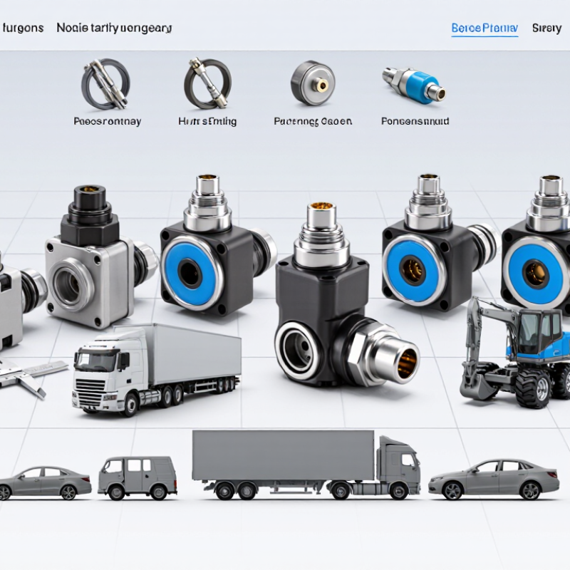
A throttle pedal sensor measures how far and how quickly the driver presses the accelerator. It does not directly control engine power. Instead, it sends pedal-position data to the engine control unit. The control unit then commands the electronic throttle actuator. This process adjusts airflow, fuel delivery, torque output, and sometimes transmission response.
Modern sensors usually contain two independent signal tracks. Their readings should rise smoothly and remain within a designed range. The control unit compares both signals to detect disagreement or sudden changes. A faulty sensor may cause delayed acceleration, limited power, warning lights, or an engine that refuses to respond. However, these symptoms can also come from wiring damage, poor connectors, or software faults. A sensor can look clean and still fail internally. That detail is easy to miss.
Tips: Check live pedal data before replacing parts. Press the pedal slowly and watch for gaps, spikes, or mismatched readings. Inspect the connector for moisture, loose terminals, and stretched wires. Use the vehicle’s service specifications, not assumptions from another model. After installation, confirm calibration when required. A short road test matters. It can reveal hesitation that a stationary test misses. I would also record fault codes before clearing them; memory often provides useful evidence.

Electronic throttle pedal sensors translate pedal movement into electrical signals. Most assemblies use two independent sensing tracks inside one housing. Hall-effect elements are common, although some designs use contact-based resistive tracks. As the pedal arm moves, each track changes its output voltage. The engine control unit reads both signals continuously.
The two signals usually follow different voltage ranges or directions. This gives the controller a comparison point. If one signal rises unexpectedly, or the pair disagrees, the system can reduce throttle authority. A warning light may appear, and the vehicle may enter a limited-power mode. That response protects against unwanted acceleration. It also shows why sensor accuracy matters more than a low purchase price.
For buyers, inspect connector quality, sealing, mounting shape, and stated operating voltage. A sensor may fit mechanically but still produce the wrong signal pattern. Check the technical sheet and vehicle application carefully. During diagnosis, a scan tool can display pedal percentages, while a multimeter may reveal unstable voltage. Move the pedal slowly. Watch for sudden jumps or dead spots. The test is useful, but not perfect; wiring faults can imitate sensor failure. Heat, moisture, and repeated pedal cycles also influence long-term performance. A careful supplier should provide test data, compatibility details, and traceable quality checks.
This comparison covers sensor designs and signal configurations rather than specific branded products. Actual compatibility, output ranges, diagnostics, and environmental ratings vary by vehicle and manufacturer; confirm them against the vehicle’s technical requirements.
| Rank | Sensor design or configuration | How it works | Typical signal arrangement | Main advantage | Buyer considerations |
|---|---|---|---|---|---|
| 1 | Dual-channel Hall-effect sensor | A magnet attached to the pedal mechanism moves relative to Hall-effect sensing elements, producing electrical signals that vary with pedal travel. | Two independent position signals; their relationship is defined by the vehicle’s control system. | Contactless sensing avoids a sliding electrical contact. | Check the required voltage ranges, channel relationship, connector, mounting, and diagnostic strategy. |
| 2 | Dual-channel inductive sensor | Pedal movement changes the coupling between an excitation coil and sensing elements; electronics interpret the change as position. | Typically provides redundant position information through two channels. | Contactless operation can reduce wear at the sensing interface. | Confirm that the vehicle controller supports the sensor’s specific interface and signal characteristics. |
| 3 | Dual-track potentiometric sensor | A moving contact travels along resistive tracks, changing the voltage measured at each track’s output. | Two tracks provide separate position signals, often with a specified correlation. | Straightforward resistive sensing with a well-established operating principle. | Because the contacts move across resistive elements, wear and contamination are relevant design considerations. |
| 4 | Dual-channel magnetic sensor with inverse outputs | Magnetic sensing elements measure pedal position and produce two channels designed to move in opposite directions. | One signal rises while the other falls over the operating range, subject to specified tolerances. | A controller can compare the channels to identify certain signal discrepancies. | Inverse-output behavior is not universal; match the exact transfer functions required by the vehicle. |
| 5 | Dual-channel magnetic sensor with same-direction outputs | Two magnetic sensing channels measure pedal travel and produce signals that change in the same direction. | Both channels generally increase or decrease together, with distinct scaling or ranges as specified. | Provides redundant position information in a configuration used by some control systems. | Do not substitute for an inverse-output unit unless the controller is designed for the same-direction relationship. |
| 6 | Analog-voltage output sensor | Internal sensing electronics convert pedal position into one or more continuously varying voltage outputs. | Analog signal levels are interpreted by the receiving controller. | Can integrate with controllers designed for analog position inputs. | Verify supply voltage, output range, reference and ground requirements, and fault-detection thresholds. |
| 7 | PWM-output sensor | The sensor represents position through a pulse train whose duty cycle varies with pedal travel. | Pulsed digital waveform; the receiving controller interprets its timing characteristics. | Can provide a position signal in a form suited to compatible electronic inputs. | Confirm frequency, duty-cycle range, electrical levels, and controller compatibility; these are application-specific. |
| 8 | SENT-output sensor | The sensor transmits encoded position information using the Single Edge Nibble Transmission protocol. | Digital pulse-based communication defined by the applicable implementation. | Can carry encoded sensor information over a digital interface. | Requires a compatible receiver and agreement on protocol settings, message content, and diagnostics. |
| 9 | Contactless magnetoresistive sensor | A magnetic field changes the electrical resistance of sensing elements; onboard electronics convert that change into position data. | May provide analog or digital outputs, depending on the design. | Contactless position measurement with flexible electronic signal options. | Check magnetic design, output format, operating conditions, and the vehicle’s required channel arrangement. |
| 10 | Integrated pedal module with position sensing | A pedal assembly combines the mechanical pedal, return mechanism, and one or more position-sensing elements. | Output and redundancy depend on the integrated sensor and vehicle specification. | Designed as a matched assembly, which can simplify mechanical fitment when the application is correct. | Confirm pedal geometry, mounting points, connector, travel range, and electrical specification before selection. |
10 Best Throttle Pedal Sensors for Global Buyers
A throttle pedal sensor should match the vehicle’s control system, not just its connector. Check the output type, pin layout, operating voltage, and signal range against the vehicle’s service data. A plug that fits can still carry the wrong signal. That detail is easy to miss.
Compare response consistency across the pedal’s full travel. A suitable sensor should provide a smooth, repeatable signal, without sudden jumps or dead spots. Ask for test data or a clear inspection procedure, and check whether the unit has been calibrated. Small variations may matter when the control system expects closely matched signals. Specifications alone do not tell the whole story.
Durability matters, too. Look for a sealed housing, secure terminals, and materials suited to the vehicle’s temperature and vibration conditions. For international sourcing, confirm packaging, traceability, and technical documents are clear and available in a usable format. Verify warranty terms before ordering. Not every seller provides the same level of detail, and that can complicate troubleshooting later. Compare total fit and support, not only price. A lower-cost option may work well, but I would want evidence before treating it as equivalent.
Ten Throttle Pedal Sensors for Buyers in Global Markets
Global buyers need to compare fit, signal design, and operating conditions—not just price. OICA reported approximately 93.5 million motor vehicles produced worldwide in 2023, underscoring the scale and variety of vehicle applications. Meanwhile, the International Energy Agency’s Global EV Outlook 2024 estimated electric-car sales exceeded 17 million in 2024. That shift makes careful application checks essential: many electric vehicles still use accelerator-pedal position sensors, though their surrounding control systems differ.
A practical shortlist can cover ten configurations: single-track, dual-track, contactless Hall-effect, inductive, sealed connector, compact housing, extended-temperature, custom-output, vehicle-specific, and service-replacement sensors. These are selection categories, not interchangeable parts. Check connector keying, mounting points, voltage range, output correlation, and pedal travel against the vehicle specification. For fleet procurement, request documented calibration, environmental test results, and traceable production batches. Ask suppliers how they handle out-of-range signals. Small details matter.
Dust, condensation, and repeated foot pressure can expose weak sealing or inconsistent return action. Bench-test samples across the full pedal sweep before approving a shipment. Compare readings at several positions, not only at rest and full travel. A minor voltage mismatch can trigger a fault or impair drivability. I have seen specifications look complete while omitting connector orientation. That is easy to miss. Regional service access, packaging durability, and clear installation instructions also affect lifecycle cost. References: OICA, 2023 Production Statistics; IEA, Global EV Outlook 2024.
Typical response-time benchmarks for common automotive throttle pedal sensor configurations
This comparison uses representative automotive engineering values. Contactless dual-channel Hall-effect configurations generally provide fast response, redundant signal output, and improved durability for global vehicle applications. Lower response time indicates faster signal transmission from pedal movement to the electronic control unit.
Choosing among the 10 best throttle pedal sensors starts with vehicle compatibility, not price. Confirm the original connector, mounting points, pedal travel, output voltage, and dual-channel signal pattern. SAE J1979 diagnostic guidance supports checking live data through standardized diagnostic communication, but connector similarity alone proves little. A sensor may fit physically yet fail after software validation. That mistake is common.
Installation should follow the vehicle service procedure. Disconnect the battery when required, protect wiring from sharp brackets, and avoid forcing the terminal lock. After fitting, perform the specified pedal-learning or throttle calibration routine. The ISO 26262 functional-safety framework emphasizes independent signal plausibility, so both sensor channels should respond smoothly during a scan. A short road test matters. Check idle response, gradual acceleration, and emergency fallback behavior.
Maintenance is mostly preventive. Inspect moisture, dust, bent terminals, and harness tension during scheduled servicing. The U.S. EPA’s 2023 Automotive Trends Report recorded about 26.4 miles per gallon for average new vehicles in the 2022 model year, showing how precise control supports efficiency targets. That figure does not measure pedal sensors directly, but it explains why small signal errors matter. Replace a sensor when readings jump, disagree, or remain outside service limits. Do not clean the sensing element aggressively. I have seen unnecessary cleaning create more faults than it removed. The better practice is careful diagnosis, documented voltage readings, and a final fault-code check.


All of Hapco's formulations are completely free of Mercury.

Hapco has been in business for over 50 years!

*NOTICE* Hapco will be will be closed on Monday, May 26th, in observance of Memorial Day. |
| Cookie | Duration | Description |
|---|---|---|
| cookielawinfo-checkbox-analytics | 11 months | This cookie is set by GDPR Cookie Consent plugin. The cookie is used to store the user consent for the cookies in the category "Analytics". |
| cookielawinfo-checkbox-functional | 11 months | The cookie is set by GDPR cookie consent to record the user consent for the cookies in the category "Functional". |
| cookielawinfo-checkbox-necessary | 11 months | This cookie is set by GDPR Cookie Consent plugin. The cookies is used to store the user consent for the cookies in the category "Necessary". |
| cookielawinfo-checkbox-others | 11 months | This cookie is set by GDPR Cookie Consent plugin. The cookie is used to store the user consent for the cookies in the category "Other. |
| cookielawinfo-checkbox-performance | 11 months | This cookie is set by GDPR Cookie Consent plugin. The cookie is used to store the user consent for the cookies in the category "Performance". |
| viewed_cookie_policy | 11 months | The cookie is set by the GDPR Cookie Consent plugin and is used to store whether or not user has consented to the use of cookies. It does not store any personal data. |