How to Choose the Right Check Valve in 2026
Choosing the right Check Valve in 2026 starts with the system, not the catalog. A valve that works well on a clean water line may behave differently with hot condensate, viscous fluid, or entrained solids. The wrong choice can bring water hammer, noisy closure, excess pressure loss, or repeated maintenance. Small details matter.
R. W. Zappe, author of the Valve Selection Handbook, is a recognized valve-selection reference. A concise paraphrase of his selection approach is: “Choose for the service conditions, not the valve name alone.” Treat that as guidance, not a verbatim quotation. Before comparing swing, lift, dual-plate, or spring-assisted designs, define the fluid, operating pressure, temperature, flow range, installation position, and acceptable reverse leakage. Also check the piping layout. A cramped line or short run near a pump discharge can affect closure behavior.
Then compare materials, end connections, cracking pressure, maintenance needs, and applicable specifications. Ask suppliers for documented performance data, and verify that the proposed model suits the actual operating envelope. A datasheet is useful. It is not the whole story. One detail is easy to underestimate: frequent starts and stops can expose a poor match that steady operation hides. Be willing to revisit the first choice when field conditions differ from the design assumptions. That reflection is practical, not a weakness. This guide will help readers assess those trade-offs and choose a Check Valve with clearer, evidence-based criteria.
Set Design Pressure and Temperature Using ASME B16.34 Ratings
How to Choose the Right Check Valve in 2026
Set Design Pressure and Temperature Using ASME B16.34 Ratings
A check valve’s pressure class is not a single pressure limit for every temperature. ASME B16.34 pressure-temperature tables assign ratings by material group, class, and temperature. For example, the standard lists about 285 psig at 100°F for Group 1.1 Class 150 carbon steel. That rating falls as temperature rises. Confirm the applicable edition, material specification, and table before selecting a valve. Small detail. Big consequence.
Use the system’s design pressure and design metal temperature together. Then check whether the valve body rating covers both, including credible pressure surges. A line that normally runs at 180 psig may briefly exceed that during pump startup or rapid closure. Do not treat normal operating readings as the full design case. Also verify the selected check-valve type suits the flow direction, fluid, and expected cycling. A rating match alone cannot prevent chatter or slam.
Tips: Compare the project’s design conditions with the ASME B16.34 rating at the relevant temperature—not just the class number. Check material group carefully; similar-looking alloys may have different ratings. Record the table reference and assumptions in the datasheet. I have seen selections look correct in a spreadsheet, then fail review because someone used ambient-temperature ratings. Recheck the inputs; it takes little time.
Choose Swing, Lift, Dual-Plate, or Axial Designs for the Flow Regime
Swing, lift, dual-plate, and axial check valves behave differently as flow changes. A swing valve suits steady flow in larger lines, where its broad disc opens with relatively little resistance. But slow flow reversal can make the disc slam shut. Lift valves suit higher-pressure service and smaller lines, though their tighter passages can add pressure loss. Dual-plate valves are compact and lightweight, useful where installation space is limited. Axial valves open along the pipe’s centerline; spring-assisted closure can help reduce reverse-flow impact. No design fits every regime.
DOE’s Improving Pumping System Performance sourcebook estimates that pumping systems account for nearly 20% of global electricity use. That figure is not specific to check valves, but it underlines why unnecessary pressure loss deserves attention. Check the minimum and normal flow rates, fluid properties, mounting orientation, and allowable pressure drop. ANSI/HI 9.6.6 provides application guidance for pump-system check valves. Still, calculated flow conditions can miss real-world transients; piping layout and pump shutdown behavior matter.
Tips: Match the valve to the actual operating range, not just the pipe diameter. Ask for pressure-drop data at expected flow, and review reverse-flow behavior with the system designer. I’d treat catalog velocity limits as a starting point, not a guarantee—field conditions can surprise you.
Size by Flow Rate, Cv, Cracking Pressure, and Allowable Pressure Drop
Choosing the right check valve by pipe diameter alone is a common sizing mistake. Start with the actual operating flow, not the line’s maximum rating. Record normal and peak flow, fluid temperature, and specific gravity. For water-like liquids, Cv relates flow to pressure drop; a higher Cv generally means less resistance. Use a flow curve when available, since one Cv value can hide performance changes across the operating range. Small differences matter.
Cracking pressure is the differential pressure needed to begin opening, not the pressure loss at full flow. A spring-loaded valve with high cracking pressure may not open reliably in a low-head system. Compare expected upstream pressure with the valve’s cracking pressure, then check pressure drop at the required flow. Keep the allowable drop explicit, especially when a pump has little pressure margin. The estimate is not a verdict; field readings may disagree.
Check both ends of the operating range. Minimum flow must open the valve, while peak flow should not cause excessive loss or chatter. Confirm that the stated Cv applies to the selected size and configuration. For viscous fluids or gases, use the appropriate correction method; the water-based shortcut can mislead. Verify installation orientation and reverse-pressure rating, too. Recheck assumptions after commissioning, because actual flow may differ from the estimate.
Match Materials and Flanges: ASME B16.5 Covers NPS 1/2–24, Classes 150–2500
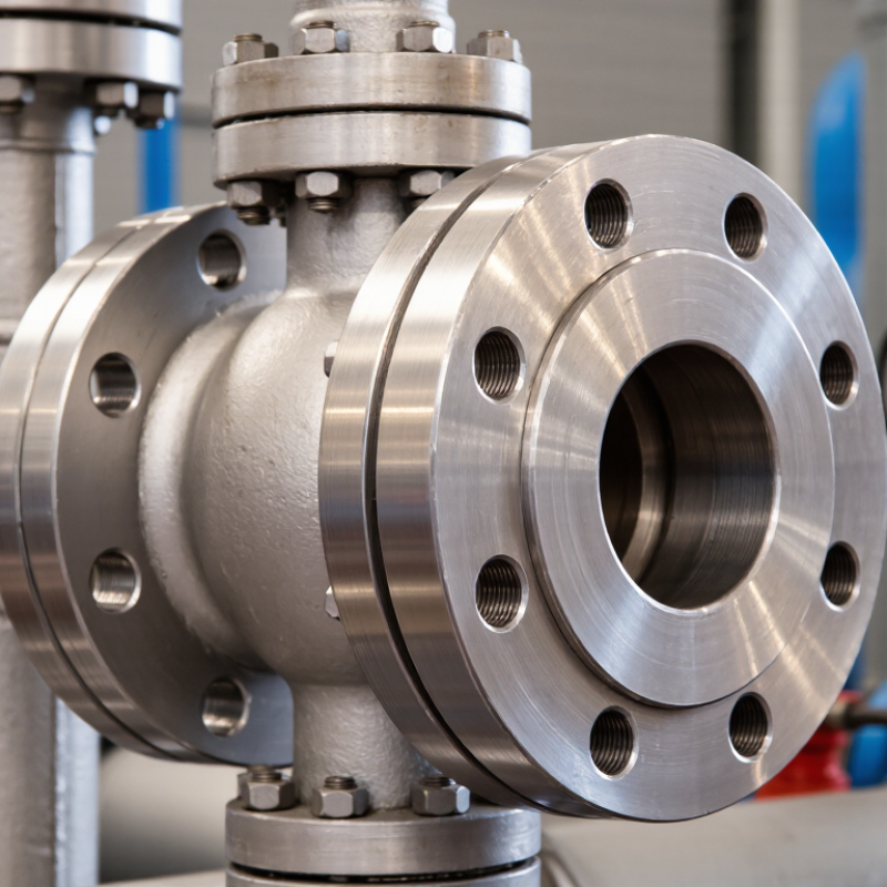
Choosing the right check valve in 2026 means matching its end connection to the piping, not just selecting a nominal size. ASME B16.5 specifies flange dimensions and pressure-temperature ratings for NPS 1/2 through NPS 24, across Classes 150 to 2500, with applicable options depending on size and material. These ranges are useful screening data, not a guarantee that every size and class combination is available. Check the valve’s flange facing, bolt pattern, and pressure class against the mating pipe flange. A mismatch may only become obvious when the parts meet on the shop floor.
Material selection matters just as much. Compare the fluid, operating temperature, pressure, and corrosion conditions with the valve body and trim materials. ASME B16.5’s pressure-temperature tables are a key reference, but they do not replace the valve manufacturer’s published limits or project specifications. A Class 150 connection, for example, should not be treated as a universal pressure rating; allowable pressure varies with material and temperature. It is tempting to choose by flange class alone. That shortcut can miss the service conditions that determine performance.
Tips: Confirm NPS, class, facing, material, and temperature together. Check the applicable ASME B16.5 tables and valve documentation before ordering. A quick flange drawing review can prevent an expensive fit-up surprise.
How to Choose the Right Check Valve in 2026
Match valve materials and flange connections. ASME B16.5 covers NPS ½–24 for Classes 150–1500 and NPS ½–12 for Class 2500.
How to read this chart: Bars show the maximum NPS within the standard’s scope for each class—not a valve pressure rating. Confirm the applicable pressure–temperature rating for the flange material, and verify that the check valve’s end connection and dimensions match the piping specification.