Liquid Molding Monthly
How to Choose Well Drilling Equipment in 2026
Choosing Well Drilling Equipment in 2026 starts with the ground, not the brochure. UNESCO’s 2022 World Water Development Report estimates that groundwater makes up 99% of Earth’s liquid freshwater. It also supplies about half of domestic water withdrawals and roughly one-quarter of irrigation water. Demand is substantial. But no single rig suits every site.
The WHO/UNICEF Joint Monitoring Programme reported that 2.2 billion people lacked safely managed drinking water in 2022. That figure highlights the importance of reliable wells, but it does not identify the right machine. Buyers must match equipment to local geology, target depth, bore diameter, and water needs. Rotary rigs can suit some formations; percussion methods may fit others. Soil samples, nearby well records, and advice from experienced drillers can help narrow the choice.
Compare more than drilling speed. Check mast capacity, torque, compressor output, available drill rods, and compatibility with the intended pump and casing. Ask how quickly wear parts can be sourced, and inspect service records where possible. A low purchase price can hide costly downtime. No rig is perfect. I would also question any recommendation that ignores maintenance access, crew experience, or changing ground conditions. The best Well Drilling Equipment is the setup that fits the site, performs consistently, and can be supported throughout the well’s working life.
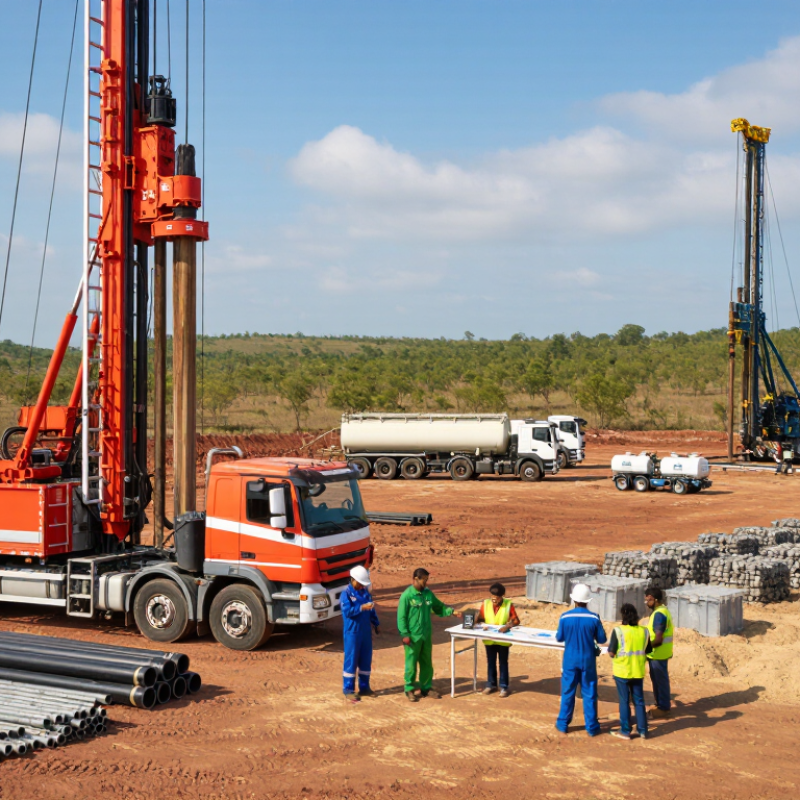
Define Well Requirements: Target Depth, Borehole Diameter, and Yield
How to Choose Well Drilling Equipment in 2026
Define Well Requirements: Target Depth, Borehole Diameter, and Yield
Before comparing drilling equipment, write down the site’s target depth, planned borehole diameter, and expected water yield. These figures shape the rig’s required torque, pullback capacity, and compatible tooling. A 90-meter target in loose sand presents different demands from the same depth through fractured rock. Local geological records can help, but nearby wells are not guarantees. Ground conditions may change over a short distance.
Diameter matters beyond the casing itself. Allow room for the casing, screen, and appropriate annular space, following qualified local guidance. Yield should reflect actual demand, such as household use or irrigation, rather than an optimistic estimate. A qualified hydrogeologist or drilling professional can help assess the aquifer and avoid sizing equipment around a guess. I have seen plans revised after the first site inspection; that is inconvenient, but cheaper than discovering a mismatch mid-project.
Tips: Confirm the target depth with local well data, then add a reasonable allowance for uncertainty. Ask the driller what formations and water levels are expected. Check that the rig and tools can handle the planned diameter at that depth, not just at shallow settings. Keep a written record of assumptions. Some will prove wrong. That record still helps guide safe adjustments.
| Well Requirement | Planning Range or Example | Equipment Implication | What to Confirm Before Selection |
|---|---|---|---|
| Target depth | Shallow: approximately 30–100 m; intermediate: 100–250 m; deeper: more than 250 m. Local geology can shift these ranges substantially. | Match the rig’s rated drilling depth and hoisting capacity to the planned depth, drill-string weight, casing program, and expected ground conditions. | Review nearby well logs, groundwater records, geological maps, and the required minimum water level or aquifer interval. |
| Ground conditions | Unconsolidated sand and gravel; mixed overburden and rock; or competent formations such as sandstone and granite. | Rotary mud drilling is commonly used in unconsolidated formations; air rotary or down-the-hole hammer methods may suit harder rock. Mixed formations may require more than one method. | Identify anticipated formation changes, cobbles, unstable layers, lost-circulation zones, and any need for temporary casing. |
| Finished borehole diameter | Common water-well casing sizes include about 100–200 mm, but local regulations and pump requirements govern the design. | Select bits, reamers, casing, and drilling tools to achieve the designed borehole diameter and allow for the casing and annular space. | Check the required casing diameter, screen dimensions, pump outside diameter, installation clearance, and applicable construction standards. |
| Required yield | Define a design flow in L/s or m³/h from actual demand. For example, 1 L/s equals 3.6 m³/h. | Yield affects well development, test-pumping equipment, pump sizing, and potentially the number or spacing of wells; drilling equipment alone cannot guarantee yield. | Use aquifer information and a properly conducted pumping test to establish sustainable yield, drawdown, and recovery. |
| Casing and screen program | Set casing and screen intervals from the expected geology and water-bearing zones; dimensions vary by site and design. | Confirm the rig can handle the required casing lengths and installation method. Provide suitable tools for placing casing, screen, and filter pack where specified. | Verify materials, wall thickness, slot size, screen placement, sanitary seals, and local requirements with the well designer. |
| Drilling fluid or air capacity | Fluid circulation and compressor requirements depend on hole diameter, depth, formation, drilling method, and cuttings removal needs. | Size pumps, mud systems, tanks, or compressors to maintain effective circulation or air lift at the planned operating conditions. | Check required flow and pressure, site water availability, fluid handling, discharge controls, and formation sensitivity. |
| Site access and setup | Consider road width, overhead clearance, ground bearing capacity, working area, and distance to water and power. | Choose a rig configuration and support equipment that can reach the site and operate safely within its constraints. | Survey access routes, turning space, setup footprint, noise limits, utility locations, and environmental restrictions. |
| Verification and testing | Plan for well development, water-level measurement, pumping tests, and water-quality sampling after construction. | Allow for development tools, a calibrated flow-measurement method, water-level equipment, and a test pump appropriate to the expected range. | Confirm test duration and reporting requirements with the project engineer or relevant groundwater authority. |
| Selection check | Base the final specification on the site-specific design rather than depth or diameter alone. | Compare rated depth, torque, pullback, mast capacity, available drilling methods, and compatible tooling against the complete well plan. | Ranges are preliminary planning guidance, not a substitute for local hydrogeological assessment, engineering design, or regulatory requirements. |


100% Mercury Free
All of Hapco's formulations are completely free of Mercury.

50 Year Track Record
Hapco has been in business for over 50 years!